 +86-15052135118

 Español
 Get In Touch


Content
- 1 The Immediate Rule for Thread Type: Coarse for Wood, Fine for Metal
- 2 Screw Lengths for 1/2-Inch and 5/8-Inch Drywall: The 5/8-Inch Penetration Rule
- 3 Ceiling-Specific Fastener Demands: Length, Spacing, and Pullout Forces
- 4 Understanding Screw Gauge and Head Design: Why #6 Is Standard and #8 Has Its Place
- 5 The Screw Spacing Formula That Prevents Cracks and Pops
The Immediate Rule for Thread Type: Coarse for Wood, Fine for Metal
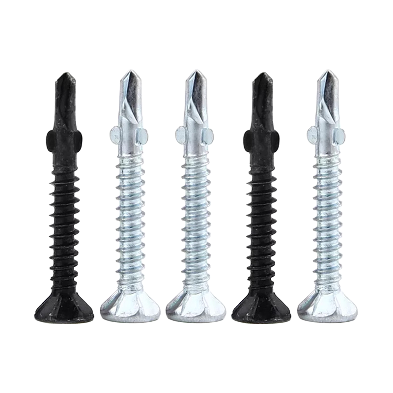
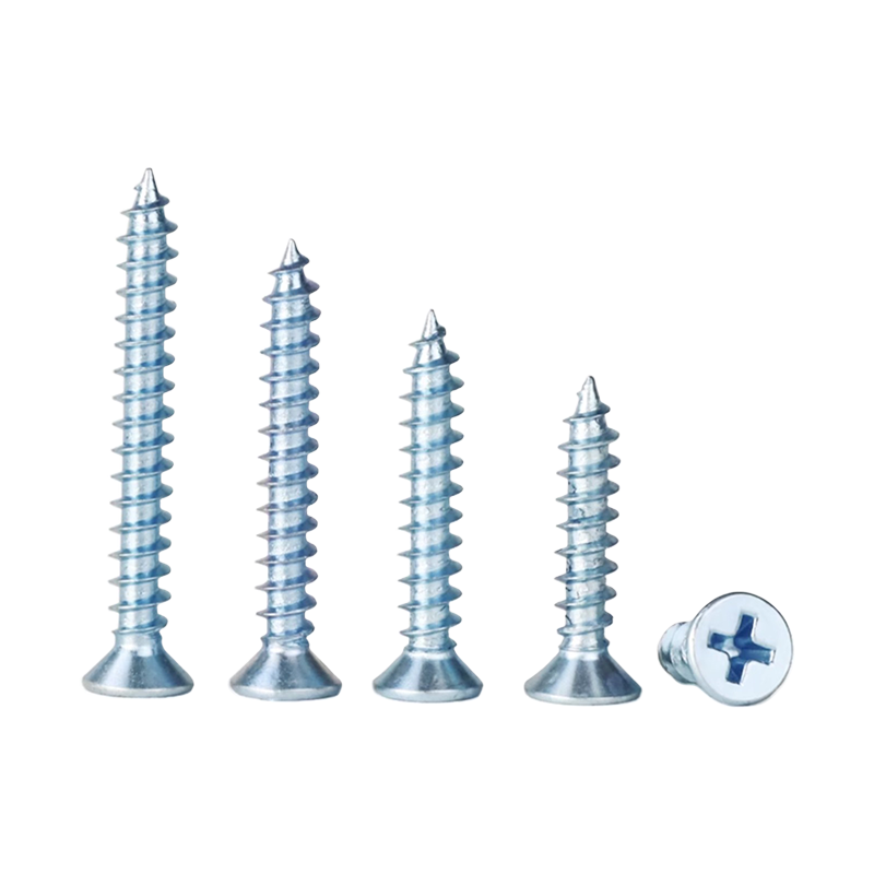
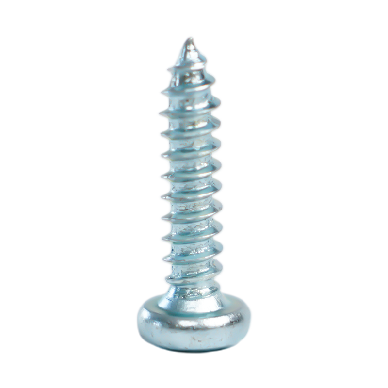
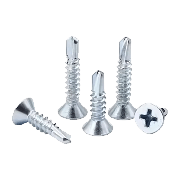
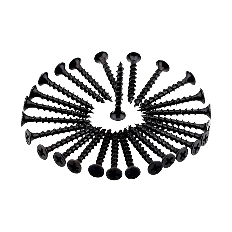
The decision between coarse-thread and fine-thread drywall screws is not a matter of personal preference — it is dictated entirely by the framing material. Coarse-thread screws, with approximately 8 threads per inch, are designed to bite into softwood and engineered wood studs. Their deeper thread profile displaces more wood fiber and provides a pullout resistance that averages 20–25% higher than a fine-thread screw of the same length in spruce-pine-fir lumber, according to testing by a major fastener manufacturer. Fine-thread screws have roughly 12–14 threads per inch and are intended for metal studs, typically 25-gauge to 20-gauge steel. The tighter thread pitch prevents the screw from stripping the thin metal as it drives and allows it to self-tap without a pre-drilled hole. Using a coarse screw in a metal stud will spin without advancing once the point breaks through; using a fine screw in wood is possible but sacrifices holding power and increases the risk of the head snapping during installation due to higher drive torque.
Screw Lengths for 1/2-Inch and 5/8-Inch Drywall: The 5/8-Inch Penetration Rule
The building code consensus across ASTM C840 and manufacturer installation guides is that a drywall screw must penetrate the framing member by at least 5/8 inch (16 mm) for walls, and many professionals target a penetration depth of 3/4 inch (19 mm) on ceilings for an added safety margin. This minimum penetration governs the screw length selection. Because the drywall itself has a thickness that must be passed through, the formula is straightforward: screw length = panel thickness + required penetration into the stud. The table below shows the standard, code-compliant screw lengths for the two most common drywall thicknesses.
| Drywall Thickness | Screw Length (Walls) | Screw Length (Ceilings) | Recommended Thread Type |
|---|---|---|---|
| 1/2 inch (12.7 mm) | 1-1/4 inch (32 mm) | 1-5/8 inch (41 mm) | Coarse for wood studs; fine for metal |
| 5/8 inch (15.9 mm) | 1-5/8 inch (41 mm) | 2 inch (51 mm) | Coarse for wood studs; fine for metal |
A 1-1/4-inch screw into 1/2-inch drywall leaves approximately 3/4 inch of thread engagement in the stud, exceeding the code minimum. For 5/8-inch drywall on ceilings, the 2-inch screw provides a full inch of penetration into the framing — a deliberate over-engineering choice because ceiling fasteners resist gravity and any potential vibrational loosening. Attempting to hang 5/8-inch ceiling drywall with 1-5/8-inch screws leaves less than the minimum 5/8-inch penetration and is a documented cause of screw pops and sagging failures over time.
Ceiling-Specific Fastener Demands: Length, Spacing, and Pullout Forces
Ceiling installations apply a continuous tensile load on every screw, which is why both the length and the pattern density increase relative to walls. A single screw in a ceiling must resist the dead weight of the panel plus any insulation or light fixture backing. The pullout strength of a coarse-thread #6 screw in a spruce stud is approximately 40–55 pounds per inch of thread engagement. For a 1-5/8-inch screw holding 1/2-inch drywall on a ceiling, the effective pullout resistance is roughly 150–180 pounds per screw, providing a substantial safety factor when spaced correctly.
Spacing is tightened on ceilings to address this tensile load. The standard perimeter screw spacing for walls is 8 inches on center, with field spacing at 12 inches on center. For ceilings using 1/2-inch drywall, the field spacing is reduced to 8 inches on center for screws, and many building inspectors require 5/8-inch Type X fire-rated panels on ceilings to be screwed at 7 inches on center in the field. This translates to approximately 48–52 screws per 4x8-foot sheet on a ceiling, versus 32–36 screws for the same sheet on a wall, doubling the number of fasteners that carry the load in tension.
Understanding Screw Gauge and Head Design: Why #6 Is Standard and #8 Has Its Place
The vast majority of drywall screws sold in North America are #6 gauge, with a shank diameter of approximately 0.138 inches (3.5 mm). This gauge is optimized for general drywall attachment: it drives quickly, creates a dimple without tearing the paper facing, and provides sufficient shear strength for normal residential and commercial partitions. A #8 gauge screw, with a shank diameter of approximately 0.164 inches (4.2 mm), is specified in two primary scenarios — when attaching multi-layer fire-resistant assemblies, or when driving into particularly dense engineered lumber such as LVL or glulam where the increased torsional strength of the thicker shank prevents breakage during installation. The table below clarifies when each gauge is appropriate.
| Screw Gauge | Shank Diameter | Typical Application |
|---|---|---|
| #6 | 0.138 in (3.5 mm) | Single-layer 1/2" or 5/8" drywall on wood or light-gauge metal studs |
| #8 | 0.164 in (4.2 mm) | Double-layer or shaftwall assemblies, dense LVL studs, fire-rated head-of-wall details |
The screw head profile is equally important. A bugle head, with its gradual curved transition from shank to head, is standard because it compresses the gypsum core and paper facing into a controlled dimple without cutting through the surface. Flat-head or pan-head screws are not suitable for drywall; they will tear the paper and create an un-finishable depression. Field observations from a major drywall contractor's quality assurance program found that using incorrect non-bugle head fasteners was responsible for over 60% of nail pops and visible fastener defects identified during one-year warranty walkthroughs.
The Screw Spacing Formula That Prevents Cracks and Pops
Beyond the thread and length selection, consistent fastener spacing is the single largest determinant of long-term surface quality. Gypsum panels expand and contract with humidity changes, and the screws act as fixed anchor points. Crowding screws too closely along the edges concentrates stress and can cause linear cracking along the joint; spacing them too widely leaves unsupported panel edges vulnerable to deflection and nail pops. The industry-standard spacing, derived from ASTM C840 and upheld by the Gypsum Association, is:
- On the perimeter of each sheet: screws placed every 8 inches (200 mm) on center, with the first screw no more than 3/8 inch from the edge to avoid edge breakage.
- In the field of the sheet: screws placed every 12 inches (300 mm) on center for walls, and every 8 inches on center for ceilings as noted above.
- For butt joints where two non-tapered edges meet, maintaining the 8-inch perimeter spacing is critical because there is no tapered recess to absorb the tape and compound thickness.
These numbers correspond to approximately 32 screws per 4x8 sheet on a wall and 48 screws per sheet on a ceiling. Driving screws at a slight angle, or "toenailing," into the stud is not permitted under code because it reduces the effective thread engagement and creates an uneven dimple that finishers must float out over a larger area. Each screw should be driven perpendicular to the panel surface until the head sits approximately 0.5–1.0 mm below the paper surface, forming a shallow dimple without breaking the paper. This is the precise condition that allows a thin layer of joint compound to conceal the fastener completely while maintaining full structural connection.